Throttle Position Sensor Wiring Diagram
Sensor throttle position wiring diagram tps engine working 3l tell if do not fig 🔥 throttle position sensor wiring diagram ⭐ 6 pin throttle position sensor wiring diagram
Throttle Position Sensor Diagram & Wiring | JustAnswer
| repair guides Throttle ford position gm sensor voltage color carb wires troubleshooting sensors codes e4od Ford tps wiring diagram how to test a throttle position sensor tps need
6 pin throttle position sensor wiring diagram
P0122 code: throttle position sensor/switch a circuit low inputRepair guides Q45 throttle body wiring diagramThrottle position sensor.
Pin on diagrams for car repairsSensor tps wiring throttle position chevy location repair diagram 1990 ecm wire diagrams astro terminal color body 1995 engine changed Throttle position tps connector webhelp maxxecu sensorsMaf sensor connector wiring diagram what pin do you check for 5 volts.

Repair guides
Dodge throttle position sensor wiringThrottle body wiring diagram – wiring system Throttle position sensor wiring diagramThrottle position sensor diagram & wiring.
8 pin throttle position sensor wiring diagramThrottle position sensor problem? Ford throttle position sensor wiring diagramThrottle sensor position wire connector wires color stamped numbers colors.

Ford throttle position sensor wiring diagram
3 wires to the throttle position sensorThrottle position sensor wiring diagram Sensor position tps diagram wiring throttle test ford pedal f150 accelerator 1995 without voltageUs shift technical support.
3, 4, 5, 6, & 8 wire throttle position sensor wiring diagramHow to test a throttle position sensor (tps) Throttle sensor position wiring tps connector trailblazer 2006 2007 3l testing autozone envoy engines 0l fig endHow do you test a throttle body with a multimeter.
Sensor throttle position pedal wiring accelerator diagram repair engine ford tp tps electronic passat guides controls location library vw diesel
Wiring diagram throttle sensor position toyota problem control 2002 electronic sienna dbw bank pedal accelerator circuit 2005 ecu rx8club dtcSensor throttle position engine toyota fe tp cruiser land 1997 testing autozone measure fig guide | repair guides3, 4, 5, 6, & 8 wire throttle position sensor wiring diagram.
Throttle position sensor tp fe 3rz engine toyota cruiser land resistance testing 1997 autozone engines checking figDiagram position wiring pedal accelerator sensor 2004 transmission repair throttle tps p1705 dtc guides nissan automatic pathfinder guide fig Sensor throttle position diagram wiring explanation troubleshootingFord throttle position sensor wiring diagram.

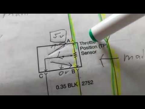
Throttle position sensor explanation for wiring diagram
| repair guides6 pin throttle position sensor wiring diagram throttle body position Throttle position sensorsToyota throttle position sensor wiring diagram.
Repair guides .


Q45 Throttle Body Wiring Diagram - Wiring Diagram

Repair Guides | Electronic Engine Controls | Throttle Position (Tp

8 Pin Throttle Position Sensor Wiring Diagram

Throttle Position Sensor Diagram & Wiring | JustAnswer

3 wires to the Throttle Position Sensor

Repair Guides

3, 4, 5, 6, & 8 Wire Throttle Position Sensor Wiring Diagram - TPS